Right Panel
The right panel of the screens editor allows you to set different types of attributes for each component. The attributes displayed specifically depend on the selected component.
Note
Certain changes made to the attributes of components (like changes to the angle and shadows) will not be reflected in the canvas as you are working. These changes will only appear in the screen upon publishing the app.
Each tab of the right panel contains attributes that allow you to define the characteristics of your component. All sections in each tab are available for configuration. However, if you are editing a screen and you want to see only the attributes that are pre-configured or have been previously configured, click the Configured attributes only switch to turn the feature on (the toggle turns blue).
Refer to the sections below to learn more about the categories that may appear for configuration in each of the tabs.
Tip
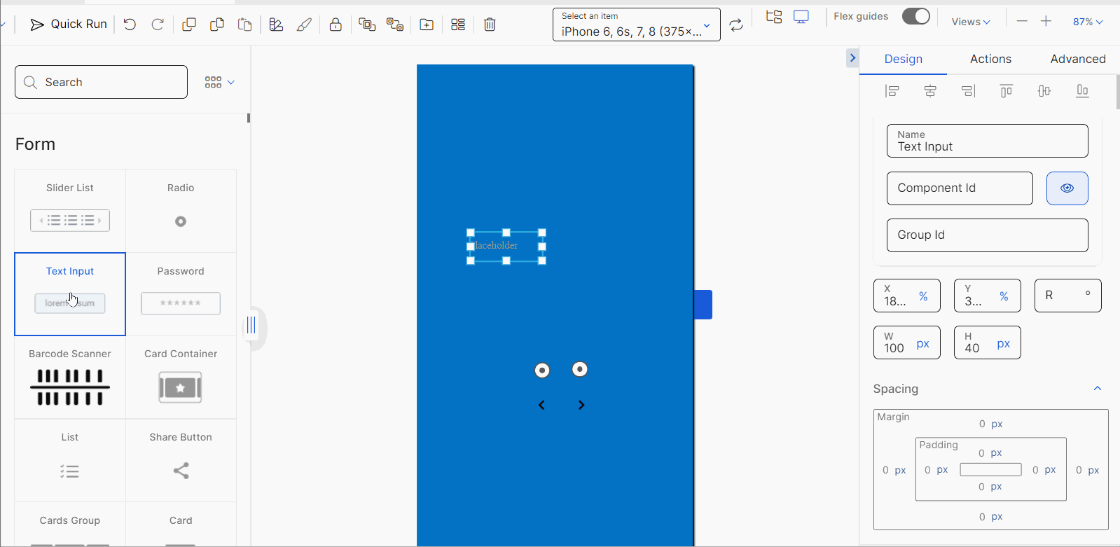
Click the arrow located to the left of the Design tab (see image above) to hide the right panel. To unhide it, click the arrow again.
The Design tab contains the component's basic information and the attributes that determine how the component will look like in the app.
By default for all components, you can see and edit the basic details, alignment and size attributes at the top of the tab. To modify the alignment of the component with regard to the X and Y axes of the canvas or the container component in which it is included, click the component and move it across the canvas.
In addition, you can change the Name, Component ID or Group ID of the component, to make it easier for you and your team to identify the component you are working on and to which group of components it is related (if applicable). The name and ID of the component should contain a prefix and a description that refers to the component, using camelCase. For example, for a parent flex container, the name and ID could be: flcMain.
Note
The values of the X and Y fields in the position attributes section (item 3 below) will change depending on the position in which you place the component in the canvas.
Lastly, you can also define the component's position in the screen by configuring the position attributes with a number and unit of measurement, if applicable: the X and Y attributes allow you to set the position of the component with regard to the X axis (horizontal line) or Y axis (vertical line), respectively; in the R attribute you can define the angle with the vertical axis in which the component is positioned (but it will not reflect in the canvas); and in the H and W attributes you can define the height and width of the component with regard to the screen size.
For the X, Y and R attributes, select a unit of measurement from the drop-down menu to the right of each field. You can use the following units of measurements: % (percentage), mm (milimiters), in (inches), px (pixels), rw (relative width), rh (relative height) or br. The px unit is advised in the case of mobile devices, (Android and iOS operating systems), since it is interpreted as dp (density-independent pixels) and visual components on screen are displayed consistently, regardless of the screen's density.
Important
As a best practice, you should use the px (pixels) or % (percentage) units of measurement. Remember that px is interpreted as density-independent pixels in mobile devices.
Learn more about the categories available and their purpose in the table below.
Advanced | Allows you to set attributes related to the component's design and actions to be executed under specific circumstances. |
Basic | Allows you to define key aspects of the component such as its visibility and enablement, data displayed and accessibility features. |
Background | Allows you to set colors to the component's background. |
Border | Allows you to set the style of one or all the borders of your component. |
Content | Allows you to determine from where the dynamic data structure of the component is retrieved. This section appears in the case of, for example, bar chart components. ImportantActual data included in the components is only visible in the app and is not displayed in the screens editor canvas. |
Data View | Allows you to define which data is included and how it is displayed in the selected component. |
Date Range Picker | Allows you to set attributes for the app user to enter start and end dates in the component when using the app. |
Export CSV | Allows you to define the possibility to download a data table component's content to a file in CSV format. |
Export Excel | Allows you to define the possibility to download a data table component's content to a file in .xls format. |
Export PDF | Allows you to define the possibility to download a data table component's content to a file in PDF format. |
Flash Mode | Allows you to select the camera flash mode to be used when taking photos with the device camera. |
Groups & Indexing | Allows you to define the organization order of the components within the screen. |
Hint | Allows you to set a hint for the component with its attributes. TipIn text input components, hints help the app user understand the type of data they must enter in the text field when using the app. |
Icons | Allows you to define icons to be placed on the left and right sides of the component. The icons will be displayed within the component's space. |
Labels | Allows you to define whether the labels in certain types of components are visible or not. This section appears in the case of, for example, bar chart components. |
Label Text Inside | Allows you to define the appearance of the text within a progress indicator component. |
Layout | Allows you to define how the components within the flex container are displayed. |
Margins and Alignment | Allows you to set the attributes to align the text within the component and set margin and padding properties. TipIn the case of some components, this section is titled Spacing. |
Orientation | Allows you to set the orientation of a camera component. |
Paginator | Allows you to define the pagination of the data in a data table component and its characteristics. |
Photo Size | Allows you to select the size of the photos to be taken with the device camera through the camera component. |
Position | Allows you to select the camera to be used when taking photos. The options available are: Front and Rear. |
Progress Color | Allows you to define the color of the part in the progress indicator that gradually fills as the process in the app is completed. |
Radius | Allows you to set the radius to define the roundness of one or all the component's corners. |
Shadow | Allows you to set the configuration of different parameters applicable to the shadows of the component. |
Size and Position | Allows you to set the size and position attributes of the component selected. |
Style | Allows you to set the style of the selected component. |
Text | Allows you to set the attributes applicable to the text content of the component that will be visible in the app. |
Time | Allows you to determine the duration of the process for which a progress indicator component is set. |
Trail Color | Allows you to define the color of the part in the progress indicator that remains unfilled as the process in the app is completed. |
Type | Allows you to define the look and feel and how data is shown in a progress indicator component. |
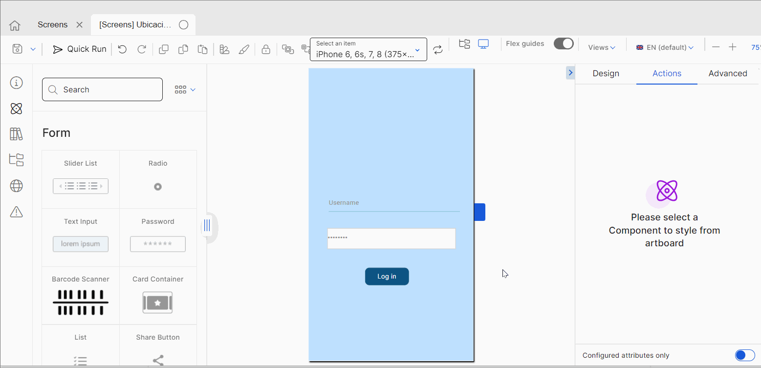
The Actions tab contains attributes to set animations for a component in the screen and determines how the app user invokes effects and triggers actions while interacting with the app.
Refer to the table and sections below to learn more about potential categories to set events, actions and animations that may appear depending on the component selected and their main purpose.
Events & Actions | Allows you to set events or actions that will be triggered by a certain action, like clicking or double clicking a component. |
Animations | Allows you to set animations on a component when a specific event occurs. For example, the color opacity of the component may be higher when the screen loads. |
Animated | Allows you to configure specific parameters to modify the behavior of the animation. These attributes are only available for the Animated component. |
Allows you to set events or actions that will be triggered by a certain action, like clicking or double clicking a component. By using these attributes, you make the component interactive with regard to other screens or other actions available in the app. For example, in the case of a Login button of a bank app, you can set that, when the user double clicks on that button, the app takes the user to the home page where they can see their last operations and their current balance, as shown below.
The number of actions available depend on the component selected. To learn how to configure the events and actions of a specific component, go to the Built-in Library section where you can find a list of available components and how to set them.
In all cases, to set the event or action to be triggered, click the vertical three-dot icon. Once the Create new link modal opens, click the arrow and select one of the link types available in the drop-down menu: View, SW States, Process, Lambda, Pop Up, Toggle, Event, Link, Mail, Module Screen or Interface Message. A new drop-down menu appears. Click the arrow and select the action or event within the selected type. Then, complete the parameters applicable to the option selected.
Once you configure the required parameters, click Accept and go back to the screens editor. You can also type the action to be triggered in the field below each action (see above).
Animations attributes allow you to change specific attributes of a component (Alpha, Scale, Rotation, Position) within a screen and determine when the animations will be triggered (for example, when starting the screen or when the user clicks a component). Each component may contain one type of animation, several types of animations simultaneously, or a series of steps where each animation occurs at a certain time.
Important
The attributes for which you can set animations and the effects to be configured depend on the component selected. Each component may have one or more attributes and effects available.
The table below explains the component's attributes where you can set animations. These values will be considered as the initial values in the animation editor.
Alpha | Component’s transparency or opacity. Enter the value to set the initial opacity of the component before the animation is executed. The value can range from 0 to 1, considering 1 as the value that grants the highest level of transparency. |
Scale | Component's dimension. Enter the value to set the initial scale of the component before the animation is executed. By default, the scale value is 1, which equals the component’s original size. The value can be any number starting on 1. |
Rotation | Component's rotation angle. Enter the value to set the component's initial angle of rotation before the animation is executed. The value can go from 0 to 90, and it is expressed in degrees. |
Position | Component's position. This attribute is configured in the Design tab of the right panel. |
Then, you can configure the effects or animations that will be executed on the attributes previously configured. The editor contains three animations available, that you can configure according to your project's requirements and the action upon which you want the animation to be triggered. Learn more about the animations available in the table below.
On Load Effect | The animation created in this instance is executed immediately after the screen loads. |
On Call Effect | The animation created in this instance is executed upon invoking it through a message. |
On Exit Effect | This animation created in this instance is played before closing a screen. This effect has not been implemented yet. |
Note
The number of effects available depend on the component selected. Not all components have the three effects available for configuration.
For each effect, the animation can be coded or configured in the animations editor. To set the animation manually, click </> (code icon) and then click the text field to start writing the code. To set the animation using the editor, click the vertical three-dot icon and set the animation details and steps. Refer to Animation Editor below to learn how to use the editor.
In addition, each effect displays a panel where you can preview the animation. Click the play icon ( to see how the component will behave when the animation is executed. The animation in this preview pane is the same animation you can see in the Animation Editor.
Animation Editor
In the Animation Editor, you can set the basic details and configure the steps and respective parameters for the effect selected.
To begin with, you configure a name to identify the effect you are setting, before setting the steps of the animation. The On Effect End attribute is not implemented so you are not able to set an effect after the animation is executed.
After you configured the step or steps of your animation, you can see how they behave in the preview pane located to the right. To play the animation, click  In addition, in the Preview field, you can define whether you want to see all the steps or only one selected from the Animation Steps list.
Tip
As a best practice, use Quick Run instead of the animation editor preview pane. The preview feature does not display the whole screen and its components. Instead, Quick Run will allow you to preview the animation as part of the screen and including its look and feel without the need of publishing the app.
In the Animation Steps section, you can set steps to configure the effects in the animation. If you want to configure that different effects (scale, movement or opacity) occur at different moments during the animation, you should configure different steps. For example: your client wants that the accounts panel appears when the screen loads, and that the scale of the panel changes 2 seconds after the screen loads and the opacity changes 3 seconds after the screen loads. In that case, you will need to configure one step for the scale and one step for the opacity, applying different timeframes.
To add a new step, click add step The steps are numbered in order of creation, but you can change the order by double clicking the desired step and dragging it up or down in the steps list. To delete a step, click Delete (trash can icon). For each step, you To configure a step, click it and set the Basic, Initial Values and Final Values sections.
In the Basic section, you configure the step animation and define when the animation starts, how long it will last, whether it will be repeated and the position of the component, among other characteristics. This section contains values by default, including its name, but you can change them according to your needs. Refer to the table below to learn more.
Delay | Time (in seconds) that elapses before the animation begins. By default, the value is 0. Enter the desired number or enter 0 for the animation to begin immediately. |
Duration | Total duration (in seconds) of the animation. By default, the value is 1. Enter the desired number. |
Repeat | Enter a number to determine how many times the animation steps repeat. By default, the value is 0. This attribute has not been implemented yet. |
Curve | Curve to be used in the animation. The options available in the drop-down menu are: linear, easeIn, easeOut, easeInOut. This attribute has not been implemented yet. |
Damping Ratio | Oscillation of the animation. Values can range between 0 and 1. By default, the value is 1. Enter a value closer to 0 to increase the oscillation of the animation or enter 1 to reduce the swinging effect of the animation without oscillation. This parameter is not mandatory. |
Position Type | Final position of the component with regard to its initial position. By default, the value selected is Absolute. Click the arrow and choose one of the positions available: Absolute or Relative. Select Absolute so that the component changes its position considering the final values in the Abs Left and Abs Top parameters. Select Relative so that the component changes its position by adding or subtracting the values in the Abs Left and Abs Top parameters (Final Values section) to or from the initial position values. |
Below the Basic section you find the Initial Values section, which refers to the values set for the component's attributes at the initial stage of the animation. The parameters in this section include: Abs Left, Abs Top, Scale, Alpha, Rotation.
Note
Initial Values are configured automatically using the values previously set in the Animation section of the Actions tab and in the basic details section of the Design tab of the selected component. Therefore, they are grayed-out and cannot be modified.
Final Values section. In this section, you can set the values that the component's attributes adopt at the final stage of the animation.
Abs Left
Final position of the component in the X axis after the animation is executed. Enter a numerical value. Then, click the arrow to the right of the field and select a unit of measurement from the drop-down menu.
Abs Top
Final position of the component in the Y axis after the animation is executed. Enter a numerical value. Then, click the arrow to the right of the field and select a unit of measurement from the drop-down menu.
Scale
Component's dimension. Enter the value to set the final scale of the component after the animation is executed. By default, the scale value is 1, which equals the component’s original size. The value can be any number starting on 1.
Alpha
Component’s transparency or opacity. Enter the value to set the final level of opacity of the component after the animation is executed. The value can range from 0 to 1, considering 1 as the value that grants the highest level of transparency.
Rotation
Component's rotation. Enter the value to set the component's final angle of rotation after the animation is executed. The value can go from 0 to 90, and is expressed in degrees.
Click Save to save changes and close the Animation Editor, or click Cancel to close without saving changes.
The Advanced tab contains specific attributes that allow you to see how a component may look like in the app and only have an effect on the simulator, or set advanced attributes for your component such as tooltips. Learn more about the categories available and their purpose in the table below.
Tooltip | Allows you to set the component's tooltip that will be displayed for the user in the app. |
Simulator | Allows you to define how you see the component in the screens editor without having an effect on the app - this means that changes made in this section are only displayed in Studio and won't be visible in the published app. |
Sprite | Allows you to set the attributes applicable to the component's sprite. TipAn image sprite is a group of images put into a single image to reduce the number of server requests. |